- The publications listed below form a part of this specification to the extent referenced. The publications are
referenced in the text by basic designation only.
A1) Technical Specification:
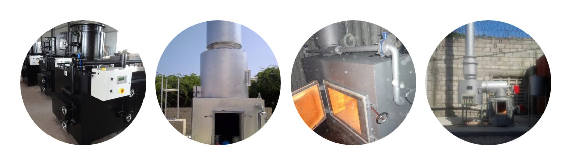
Incinerators
All types of diesel fired incinerators acceptable for HCW may be provided as long as they can
safely treat medical waste. The equipment should be compliant with all requirements for
installation in Kenya. All components for installation must be included.
Technical evaluation will consider the entire system including the treatment plant. It’ll be
the responsibility of the Bidder to provide a full system, including all necessary secondary
systems and/or additional equipment.
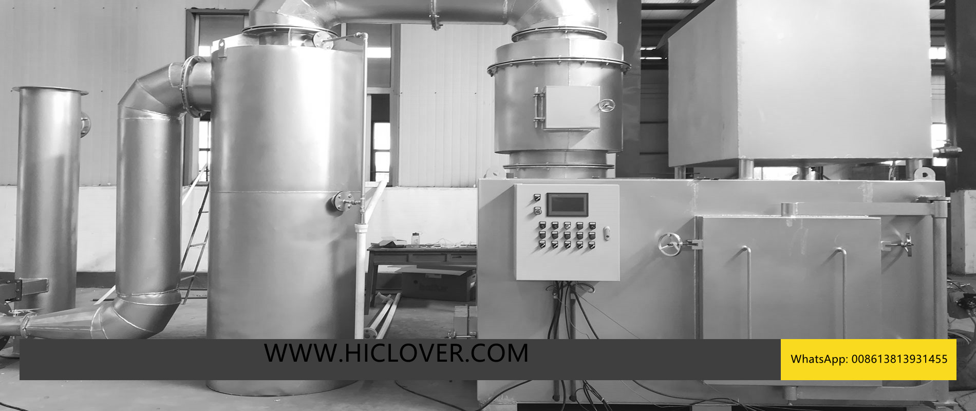
An approved plant must have four distinct sections that demonstrate three fundamentals of
Turbulence, Residence Time and Temperature inbuilt in the plant layout .The regulated segments
may include but not limited to:
Overall plant design
Feed chamber/ charging
Main Combustion Chamber
Secondary Combustion Chamber
Particulate Scrubbers
Acid Gas Scrubbers
The stack/ chimney
To the main incineration process, a static, two room system is required with a single main
combustion chamber and one flue gas afterburning chamber. The incinerator must be able to
meet these parameters:
1,100 °C
The furnace (including secondary combustion chambers etc.) dimensions must be big enough
to provide for an effective combination of gas residence time and temperature such that
- Treatment capacity of: a) 50 kg waste per hour.
- Temperature: Main combustion chamber up to 850°C, and in the second chamber > =
combustion reactions may approach completion and result in low and steady CO and VOC
- Retention Time: 2 seconds in the second chamber
emissions.
In order to avoid the production poisonous gases, the incinerator must combine the gasification or
pyrolysis phase with another combustion phase with flue-gas treatment that provides for
usable emission levels to air inside the related emission ranges defined in the criteria
5
for incinerators which are described in the ENVIRONMENTAL MANAGEMENT AND COORDINATION
(WASTE MANAGEMENT) REGULATIONS 2006 of the Republic of Kenya.
Where grates are used, it’s preferred that the design incorporates adequate cooling of the
grate such that it allows the variation of the primary air supply for the main goal of
combustion control, instead of for the heating of the grate itself.
Complete details on how the equipment matches the Technical Specification.
Include another statement with a description and calculation of all cost related to the
regular running of the plant over a 12 month period.
Full description of the system(s) being proposed.
Lay out drawing with all main equipments, flue gas ductwork and main piping.
Piping and Instrumentation Diagram.
Operation manual in the English language.
Implementation program and training concept.
Installation and maintenance program.
Detailed list associated with spare and wear part package for 2500 h operation (items which
will be included in the contract). The list should be detailed enough to allow PATH to
carry out a cost estimation.
Other information such as process description, brochures, etc. should be just added if
the information will be useful for the technical analysis of the treatment procedure.
A2) Technical Specification:
Medical Waste Autoclave
Manual autoclave with vertical loading; gravity displacement type with possibility for Vacuum.
Capacity: Up to 12 kg/h
Chamber size: >150 liters
Material: Stainless Steel
Temperature: 134 °C
Further information:
Minimum autoclave room size shall be 150 liters and shall have a usable volume
(loading basket) of 100 liters.
Shall work based on gravity air displacement principle.
The vacuum system shall be of a thermal shock kind.
6
The pressure vessels should be pressure tight, the rising of the pressure (at a beginning pressure
of below 80 mbar) shall be lower than one mbar/min.
With in-build electrical heating elements for steam generation (heating elements > 4000
Kw).
Chamber and door shall be made from high quality stainless steel (e.g. AISI 3161).
Chamber in vertical position, it shall enable a simple loading/unloading of the loading
basket. The baskets
shall be designed for the usage of non-heat resistant waste bags, a system for the
collection and controlled release of free liquids and condensate from the waste shall be
incorporated. The treatment time shall be ≥30 minutes at
105°C, ≥20 minutes using a temperature used of ≥121°C (TDes 0+4) and ≥10 minutes
using a treatment temperature of ≥ 134.
The steering of the treatment process should be semi-automatically as well as manual.
The Treatment Equipment shall be equipped with at least the following tools:
o treatment room temperature signaling instrument
o treatment room pressure indicating instrument
For treating the outgoing air, a HEPA filter together with a condensation
system should be used.
The filter will probably be built in a manner that a disinfection of the filter shall be possible in a builtin
condition.
The filters must be heat resistant, steam resistant, hydrophobic and pressure resistant for
the pressure difference.
Cooling down phase after treatment should be existent; the temperature of the waste
should be not greater than 80°C after completing the cooling down process.
The pressure vessel should be equipped with a heating insulation, the maximum outer
surface temperature should be < 50°C.
The manufacturer must provide a statement that the pressure vessel is manufactured in
accordance with relevant guidelines for pressure equipment.
After accompanying documents should be provided with the treatment system and
shall be available at the Site:
Cooling down phase after treatment should be existent; the temperature of the waste
should be not higher than 80°C after finishing the cooling down process.
The pressure vessel should be equipped with a heat insulation, the maximum outer
surface temperature should be < 50°C.
The manufacturer must provide a declaration that the pressure vessel is manufactured in
accordance with relevant guidelines for pressure equipment.
Following accompanying documents should be supplied with the treatment system and
shall be available at the Site:
- Operation instructions (including process description).
- Loading and maintenance procedures.
- Short-form of operation and loading procedures.
- P&I diagram, circuit plan, technical data sheet, pressure vessel certificate.